Distributed Acoustic Sensing
Transform standard optical fiber into a distributed vibration and acoustic sensing array. Planck DAS gives integrators a hardware and software foundation for perimeter, railway, pipeline, and infrastructure monitoring applications.

Integration-ready
DAS projects depend on local installation design, event logic, and customer workflows. Planck focuses on the sensing equipment, software modules, and integration support needed by solution builders.
Locate vibration and acoustic events along the fiber with meter-level spatial context.
Use Planck processing modules as the base layer for partner classification workflows.
Dashboard views for signal analysis, event review, and operator awareness.
Data outputs and customization support for partner monitoring platforms.
DAS software
Planck Sensing handles the optical sensing and raw data processing, so you can focus on your applications and domain expertise. Our DAS software brings processed signals, visualization, and acquisition controls together for setup, site evaluation, and application development.
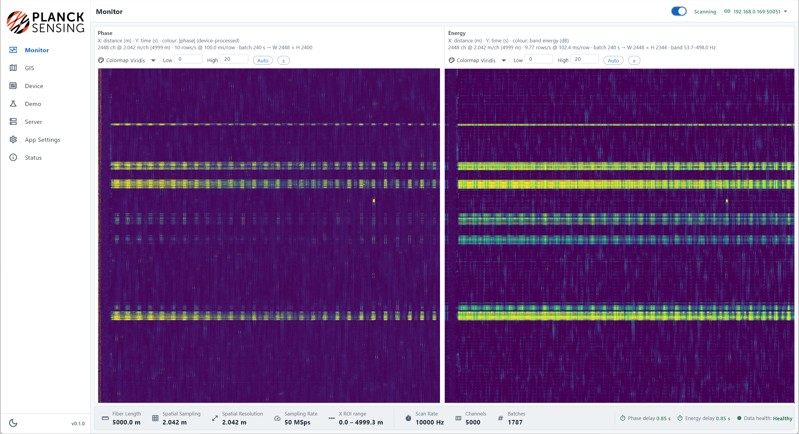
Compare device-processed phase and band-energy waterfall views across fiber distance and time. Adjustable color scales help reveal signal patterns, while scan status, data health, and acquisition details keep the measurement context visible.
Review scan rate, fiber length, pulse width, and demodulation settings in one device view. Region-of-interest and gauge-smoothing controls support configuration of the monitored section, with effective geometry displayed alongside the settings.
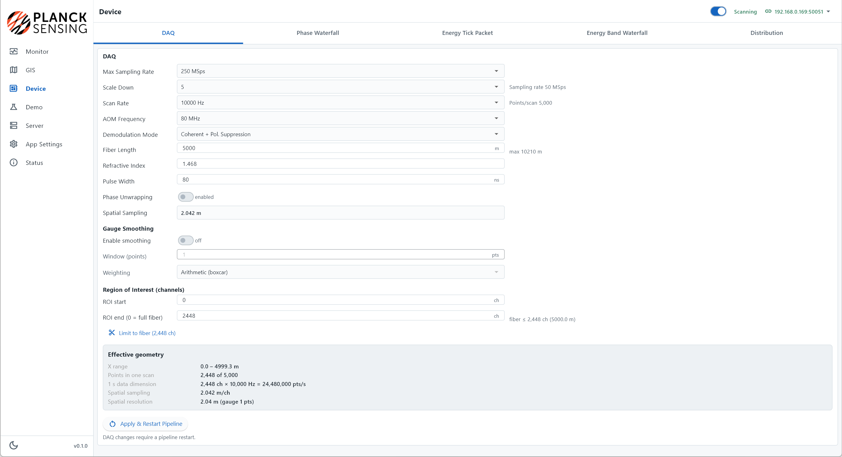
Screenshots show an example configuration. Operating parameters depend on the selected equipment and application requirements.
Coherent light pulses travel through existing or newly deployed fiber.
Vibration changes the backscattered signal along the fiber path.
Software locates and visualizes events for partner workflows.
Applications
Explore how fiber placement, vibration coupling and site conditions guide the selection and validation of a DAS monitoring system.