
Distributed temperature sensing (DTS) measures temperature along an optical sensing cable. In a tunnel, the usefulness of that profile depends on where the cable sits relative to the heat source. A route near the ceiling and a route beside power cables answer different monitoring questions. Defining those questions early helps the designer choose the sensing layout and the tests needed to assess it.
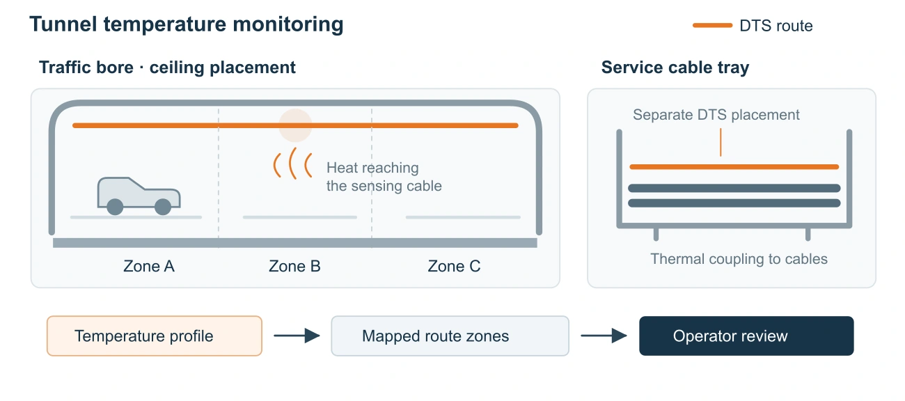
Start with the heat source
The sensing fiber responds to its own temperature. Interpreting that measurement as the temperature of nearby air or equipment requires an understanding of heat transfer into the cable assembly. Its construction and mounting influence that response.
For the traffic bore, the monitoring objective may be to observe heating that reaches the upper part of the tunnel. For an electrical cable route, the objective may be to locate heating near a particular tray or asset. These objectives call for separate placement decisions, even when both routes connect to the same monitoring installation.
Assess airflow around the ceiling route
A ceiling sensing route can record temperature changes where rising hot gases reach the cable. Tunnel geometry, ventilation and obstructions influence that exposure. Assess the proposed position against the expected airflow and the heating scenarios that matter to the operator.
Cable temperature also takes time to respond to a changing environment. A shorter measurement cycle cannot remove the thermal delay of the cable assembly. When defining an alarm requirement, consider heat transfer, measurement settings and alarm criteria together. Test the response across the airflow conditions expected during operation.
Position tray sensing near the relevant assets
A small hot spot within a cable installation may produce little temperature change at the tunnel ceiling. A tray sensing route therefore needs its own assessment of proximity and thermal contact with the asset being monitored.
Identify which cables or tray sections the route is intended to observe, then record how the sensing cable will be mounted. Verify thermal contact and coverage for each asset included in the monitoring plan. The commissioning test should reproduce the intended heat-transfer path closely enough to assess the installation. The resulting temperature profile remains a measurement at the sensing fiber; conductor-temperature estimates require a suitable thermal model.
Map fiber distance to tunnel chainage
An optical distance must be related to a physical location before an operator can act on it. Lead-in cable, spare lengths and changes in routing can affect the relationship between distance along the fiber and distance along the tunnel.
Record identifiable points along each sensing route and relate them to tunnel chainage, access points and asset references. Check those relationships after installation. Keep ceiling and tray routes distinguishable in the receiving system’s location records. A reported temperature change should direct an investigation to the appropriate tunnel section and sensing route. Update the mapping when cable routing changes.
Test the installed arrangement
Agree the acceptance checks with the operator and responsible system designer before commissioning. A focused test plan should cover:
- Representative heating at the intended ceiling and tray locations.
- The airflow conditions relevant to the monitoring objective.
- Location mapping and the handling of instrument or sensing-cable faults.
- Measurement delivery and event handling at the receiving system.
These checks establish evidence for the installed arrangement. Fire-related use also requires validation against the project’s detection and certification requirements. Include alarm delivery, control-room displays and response procedures in the system acceptance tests.
See the tunnel and highway application for the sensing layout and equipment overview, or download the application brochure.