
A power cable route rarely has uniform thermal conditions. Ducts, crossings, cable groupings and nearby heat sources can create sections that behave differently under the same circuit load. Distributed temperature sensing (DTS) records temperature along a sensing fiber, helping engineers locate those differences and review how they change over time.
Interpreting the profile starts with knowing where the fiber is installed. A temperature measured inside a cable construction has a different relationship to the conductor from one measured in an adjacent duct or in tunnel air.
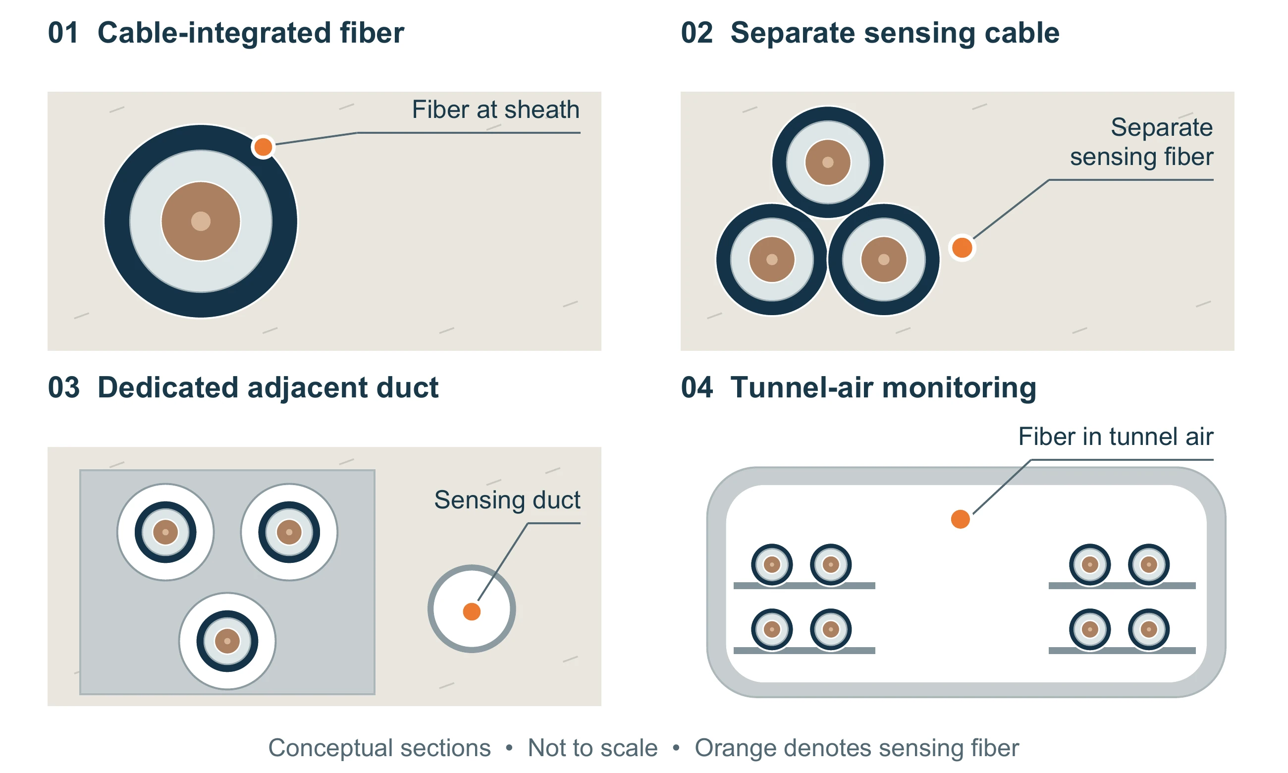
Identify the measurement location
DTS measures temperature at the fiber, not directly at the electrical conductor. Cable materials, surrounding ground and the distance from a heat source influence both the measured value and its response to a change.
For cable monitoring, record the sensing cable’s position relative to the power cable along each section. Where the installation changes—from a direct-buried route to a duct, for example—the interpretation may also need to change. A tunnel-ceiling sensing route serves a different purpose from a cable-mounted route and should not be treated as a substitute for it.
Map optical distance to the cable route
The distance shown by the instrument follows the fiber. Lead-in fiber, spare coils and changes in routing mean it is not automatically the same as physical cable chainage.
Commissioning should establish a trace-to-route map with known locations such as joints, crossings, access chambers and section boundaries. Retain the as-built records and revise them after cable or fiber work. A clear mapping makes an event useful to the inspection team: a distance alone is less helpful than a named cable section and its access location.
Read the temperature history with operating context
Investigate warm sections in the context of circuit loading, neighboring sections and recent site activity. Repeated heating at one location may justify investigation, but the cause still needs engineering review.
Temperature history helps distinguish a short event from a persistent condition. An operator view can retain the current profile alongside earlier measurements and the relevant operating records. When thermal calculations are used, distinguish fiber measurements from model estimates with clear labels and timestamps.
Select measurement settings together
Range, spatial resolution, sampling interval and acquisition time describe different aspects of the measurement. A finely sampled trace does not necessarily resolve a short hot section. Spatial resolution describes the ability to distinguish temperature changes over distance; the sampling interval describes the spacing of reported samples.
Review the expected feature size, fiber length and required update cycle together. Include lead-in fiber and any return path in the optical length. For optically switched channels, confirm the cycle for the intended channel configuration. Assess accuracy, range and update time under the operating conditions stated in the selected model’s datasheet.
Keep thermal rating separate from measurement
Conductor temperature and permissible cable loading are calculated outputs. They require cable construction, installation information, loading and a suitable thermal model, with validation for the intended use. A DTS temperature profile alone does not establish additional loading capacity.
For an initial installation, define the measurement and investigation workflow first. Agree reference-temperature checks, route mapping, data-quality indications and representative alarm tests. Any later rating function should have its own validation and operating rules. DTS supports condition assessment; it does not replace electrical protection.
See the power cable application for equipment options, or download the two-page application brochure.