
Power distribution inside a data center depends on bus ducts and busways operating reliably under changing electrical loads. Conventional protection and scheduled inspection remain essential, but they do not provide a continuous temperature profile along the complete route.
Distributed temperature sensing adds that missing layer of visibility. A fiber-optic sensing cable follows the busway and measures temperature continuously by distance, allowing the monitoring application to connect a thermal event with a named joint and physical route position.
A route-based view of temperature
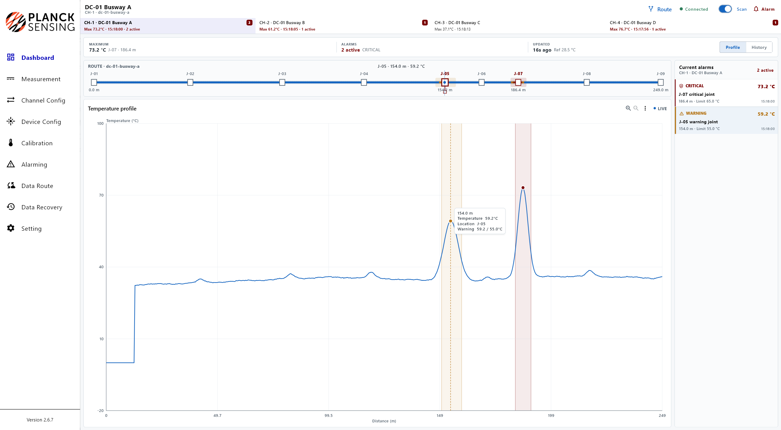
Instead of treating temperature as a collection of isolated points, DTS displays a continuous profile along the monitored busway. In the application software, each channel can represent a separate busway, while named joints are mapped to their distance positions.
When a temperature peak crosses a configured threshold, the alarm record can keep the most useful context together:
- Busway channel and route name
- Joint ID and distance position
- Alarm severity and measured temperature
- Configured limit and event time
This makes the alarm easier to relate to the physical installation and gives the operations team a clearer starting point for inspection.
Live alarms and thermal history
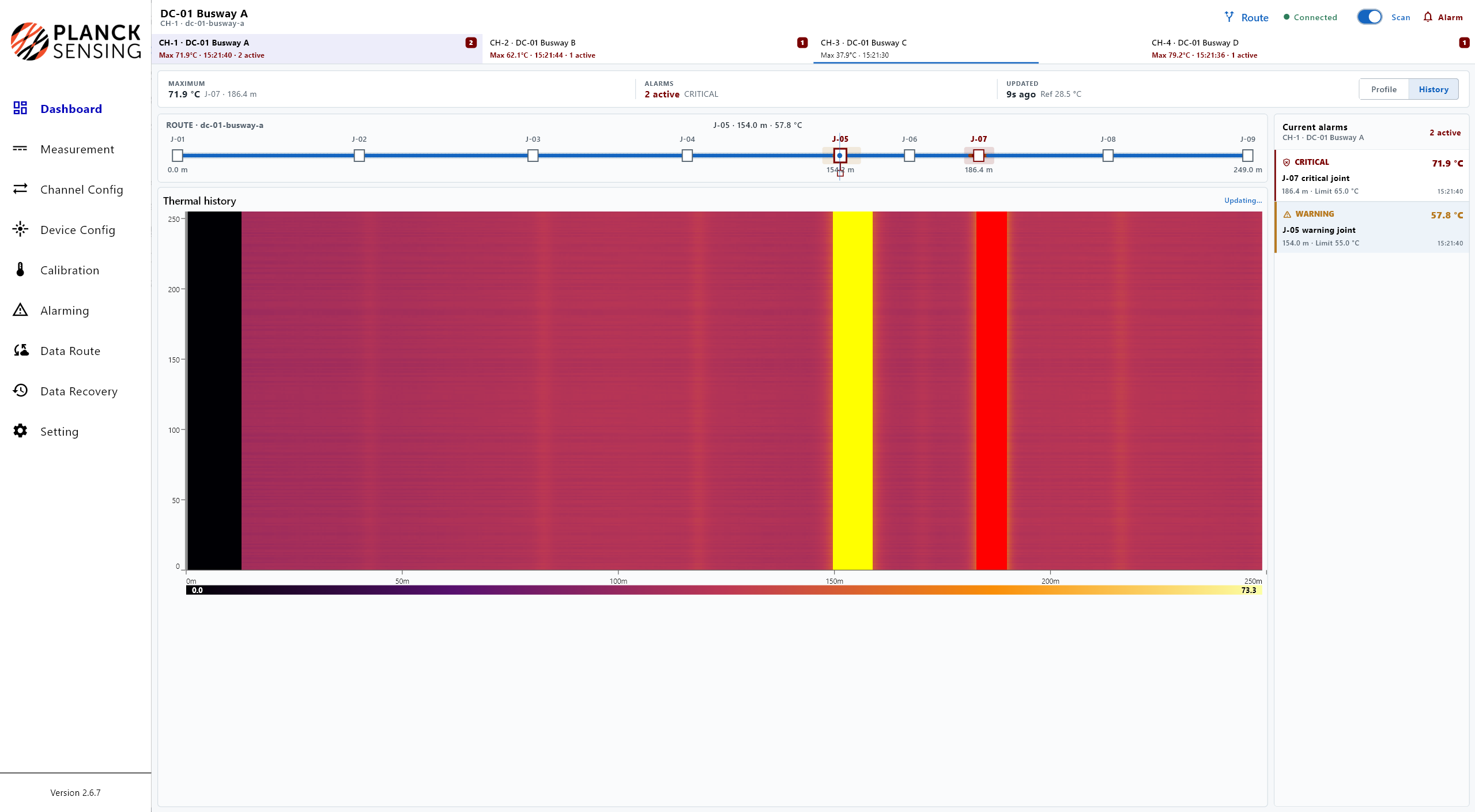
The live profile shows the current condition of the route and highlights active warning or critical zones. A thermal-history waterfall adds a time dimension: repeated heating appears as a stable band at the affected route location.
Together, these views help teams distinguish a persistent hot spot from a short-lived temperature change. They also make it easier to compare the event with busway loading, maintenance activity, or other operational records.
A practical system configuration
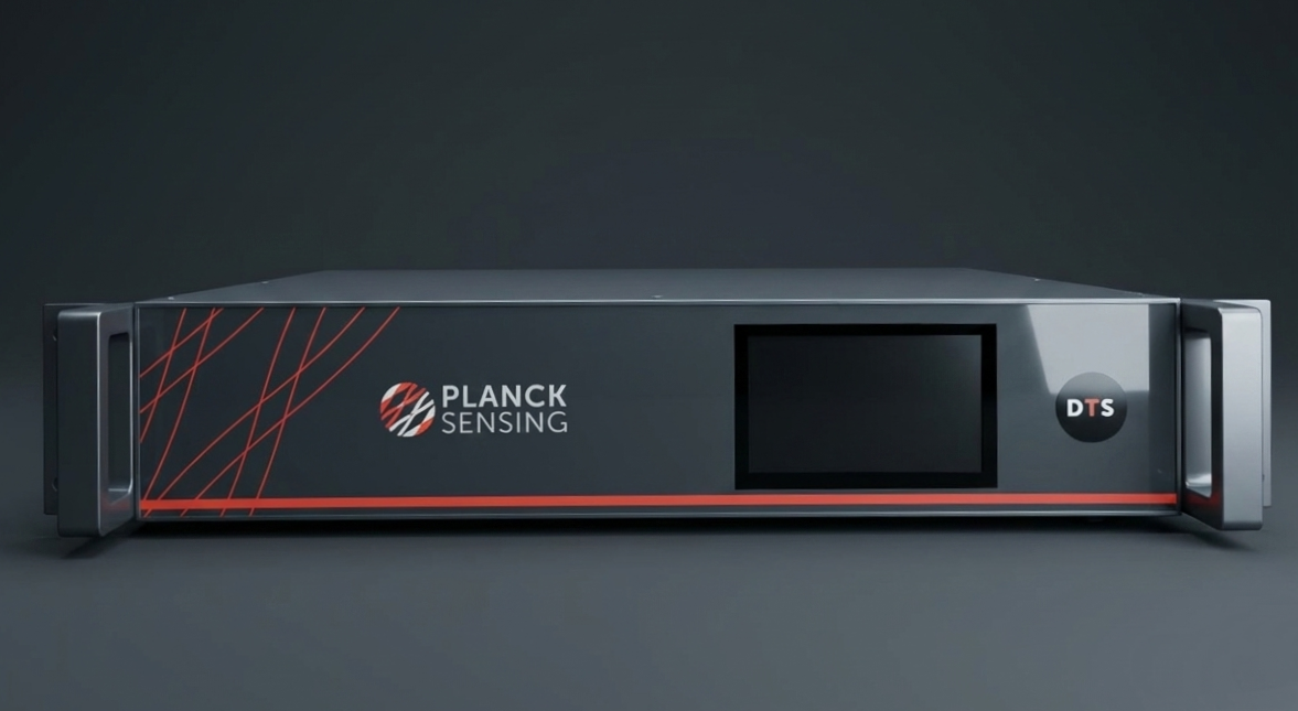
The example configuration uses a 5 km, four-channel DTS configuration with 0.3 m spatial resolution and a measurement time of 1 second per channel. Ethernet, REST API, WebSocket, and RS485 Modbus interfaces support integration with local software and data workflows, while dedicated relay outputs can provide direct alarm signaling.
The exact sensing cable, fiber route, channel allocation, and alarm thresholds depend on the busway layout and operating requirements. DTS complements existing electrical protection and inspection procedures; it does not replace them.
For a project-specific configuration, share the busway route, joint locations, required alarm behavior, and integration interface with the Planck Sensing team.
View the data center application or contact Planck Sensing to discuss your route.